MMIRS slit mask design
Tips on slit mask design for MMIRS
This page compiles some tips for slit mask design for MMIRS. The new slit mask design software, MMIRSMask, runs in the browser and is very similar to the BinoMask slitmask design for Binospec (both written by Sean Moran). You can see a walkthrough of the Binomask procedure at Binomask information. There are some differences, and suggestions that were previously embedded in the instructions for the old MMIRS mask design software, which are now compiled here.
Mask names
Try to use an identifiable and unique mask root name, like “ngc1399a”, but not “mymask1”.
Target list format
The target list should be a comma or tab delimited file with one header line and fields selected from:
name,ra,dec,magnitude,priority,pm-ra,pm-dec,epoch,type
ra, dec, and type are mandatory. name, magnitude, priority are recommended. The easiest way to format this is to have a CSV file with one header line and the desired fields. “type” should be “target” or “box”. Use “target” for your science targets and “box” for alignment stars (see below). If you use a column for priority, you need to also have priorities for the box stars so the file parses correctly, but the value is ignored; just use any number that is the same datatype as your target priorities.
Proper motions input to MMIRSMask and BinoMask web-based mask design are in mas/yr, not the seconds/century units that the MMT telescope and object catalogs use.
Alignment / box stars
Like many spectrographs, MMIRS fine-tunes the alignment of the slitmask by taking images of stars through a few boxes pre-cut in the slitmask. So you have to supply a list of box stars in the same file as your science targets, indicated with type = “box”. This is unlike Binospec, which doesn’t need box stars. The box stars are recommended to be 13.5 < H < 16 (Vega mag), to be visible in a short exposure and avoid saturation. Each box star should be the brightest star in its ~2x6" box (no ambiguous/double stars). If you select stars from Gaia, you can trim the list to avoid high proper motion stars. You can also add pm-ra and pm-dec columns to your target table, but don't forget to also fill in these columns for your science targets (even if just 0.0,0.0). The box star list should be in the same region of sky as your science targets, and cover at least as much area as one MMIRS field of view.
Slit width and length
MMIRSMask defaults to 0.7″ slitlet width and 7″ slitlet length. We recommend keeping these defaults to start. If you need higher resolution at the cost of significantly less light, you can use down to 0.4″ wide slitlets (which yield R=1400 with the HK grism). The 7″ long slitlet will allow a small dither along the slitlet. If your source density is not large, you can increase the length to 10″.
Guide stars and wavefront stars
MMIRSMask will retrieve a list of guide stars in your region of sky from GAIA, shown with blue points, so you don’t need to make a list of guide stars. The js9 display will show pairs of blue and yellow region outlines, outside the innermost rectangle of the MMIRS field of view. The blue and yellow C-shaped regions are the patrol areas of guide and wavefront cameras. To observe there must be a guide+WFS star (12 < R < 14.5) in at least one of the inner blue regions, ideally both; and a second guide star (12 < R < 16) on the other side, which can be in either the inner blue or outer yellow region.
Getting suitable guide + WFS stars can be a hard part of tuning the mask position. You may need to both drag the mask position around to get stars into the guide regions, and allow MMIRSMask the freedom to vary the PA and position to optimize the target and guide-star selection.
Checking mask design
You can zoom in to the js9 display to verify the sample of targets that were selected on slitlets, shown as cyan rectangles. Alignment boxes are indicated with small tickmarks on top of their star images. Mousing over a slit or box will show information such as the target ID. To get more control over the js9 display, select Reference Image > Show Image Controls in the menu items on the left side.
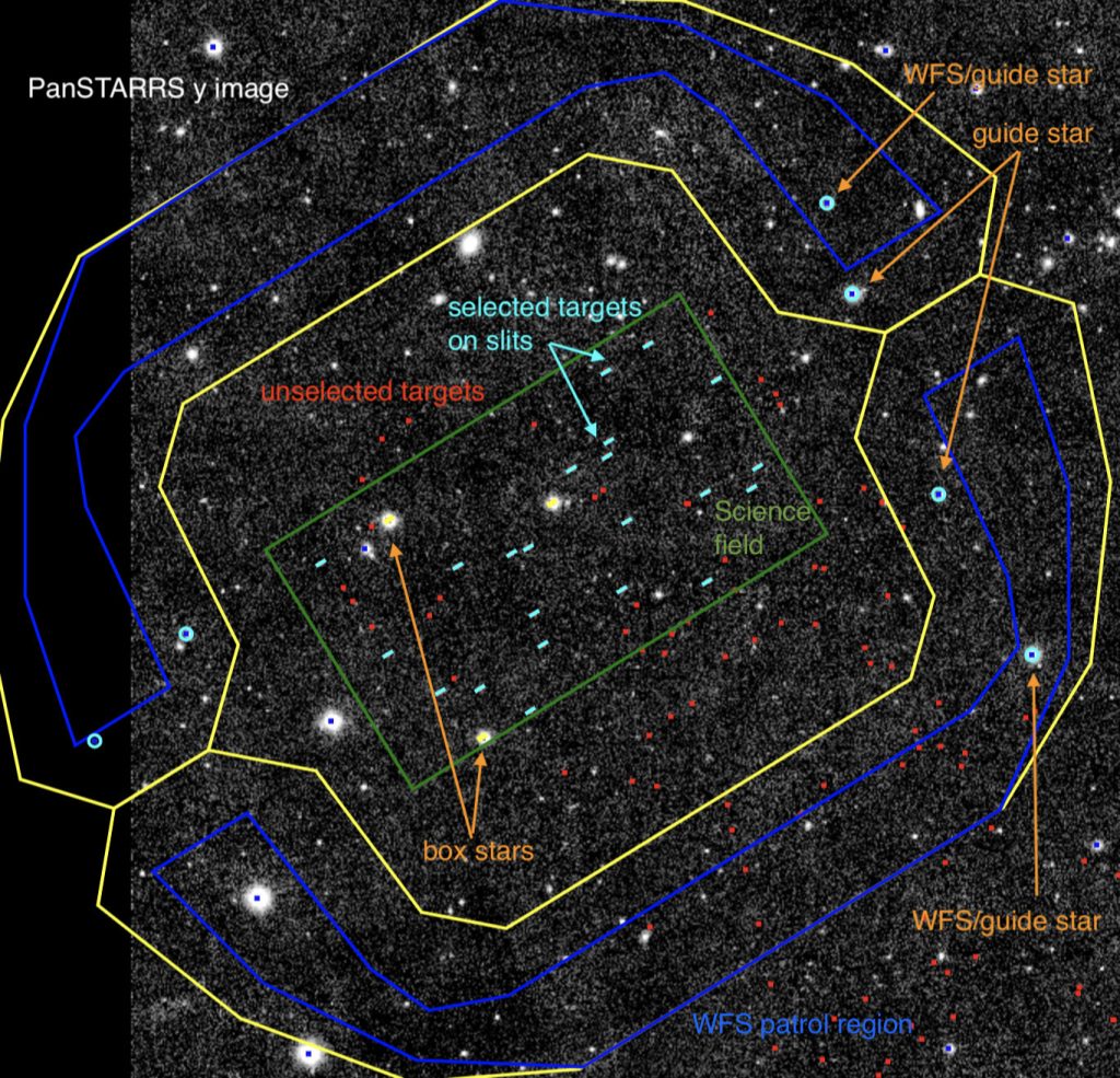
Example display of a designed mask
This screenshot of MMIRSMask after “place slits” has completed shows the outlines of the science field (inner green rectangle) and guider patrol regions (outer blue and yellow C shapes). Candidate science targets are marked with red points and candidate guide stars are marked with blue points. The targets that were actually selected onto slits are shown with cyan slitlet rectangles, and the selected guide stars are circled in cyan. You will see these points and circles once “place slits” succeeds; the text labels and arrows were added as explanation. The background image is from PanSTARRS y-band.