The Telescope Today
The 6.5-meter (21-foot) diameter MMT telescope is operated by the MMT Observatory (MMTO), a joint venture of the Smithsonian Institution and the University of Arizona. The MMT is located on the summit of Mt. Hopkins, the second highest peak in the Santa Rita Range of the Coronado National Forest, approximately 55 kilometers (30 miles) south of Tucson, Arizona.
The 6.5-meter (21-foot) diameter MMT telescope is operated by the MMT Observatory (MMTO), a joint venture of the Smithsonian Institution and the University of Arizona. The MMT is located on the summit of Mt. Hopkins, the second highest peak in the Santa Rita Range of the Coronado National Forest, approximately 55 kilometers (30 miles) south of Tucson, Arizona. The 2616-m (8585-ft) elevation at the summit places the MMT above much of the earth’s atmosphere, reducing atmospheric effects on image quality at the telescope. The MMT is on the grounds of the Smithsonian Institution’s Fred Lawrence Whipple Observatory. Whipple Observatory also operates an administration complex and Visitors Center. The MMT telescope was originally commissioned in 1979 with six 1.8-meter (5.7-foot) primary mirrors and an effective aperture of 4.5 meters (14.8 feet), being the third largest telescope at that time. The telescope underwent an extensive upgrade from 1998 to 2000, including replacement of the six mirrors with the single 6.5-meter primary mirror. The telescope enclosure also required major modifications to accommodate the large new mirror. The conversion resulted in more than doubling the light-gathering power of the telescope and an increase in the angular field of view by a factor of 15.
The MMT was one of the first of the current generation of large telescopes that use an altitude-azimuth (“alt-az”) mount, For this design, both the azimuth (i.e. horizontal) and altitude (i.e. vertical) axes are used to track celestial objects. During operation, the entire telescope building rotates, following the telescope as it moves. The result is a much more compact telescope enclosure than is possible with other types of telescope mounts. Because of the alt-az mount, the MMT more closely resembles a cube or box (see Figure 1) rather than the more traditional rounded dome of telescopes before its time. As seen in Figure 1, shutters on the front and back of the box-like telescope enclosure open to allow the telescope to observe the night-time sky. Prior to the construction of the MMT, telescopes were typically built on a equatorial mount, where one of the two telescope axes remains fixed, pointing to the celestial north pole. The height and size required for an equatorial mount makes this type of telescope design increasingly less practical for large telescopes. Following the example of the MMT, all large telescopes since the construction of the MMT have used an alt-az mount design.

The MMT is a four-story rotating building that is 63 feet long, 43 feet wide and 54 feet high. It has 7500 square feet of usable floor area plus 4000 square feet in the non-rotating basement and service area beneath the telescope. Besides the telescope chamber, the building contains a telescope control room, offices, and various laboratories. The entire building rotates on four wheels on a stationary track. The MMT building rests on a foundation of 200 cubic yards of concrete.
The 6.5-meter primary mirror of the MMT was spun-cast and polished from borosilicate glass at the Steward Observatory Mirror Laboratory (SOML) on the campus of the University of Arizona in Tucson. Borosilicate glass has very low coefficients of thermal expansion, a third of that of ordinary glass. This reduces the optical effects of temperature variations on the mirror surfaces used to reflect light. The mirror was initially cast into its overall shape in a rotating oven. It was then ground and polished to its precise optical requirements. After the mirror was transported up to the summit of Mt Hopkins, in itself a major achievement, it was placed in its custom mirror cell at the telescope. Soon after, a thin reflective coating of aluminum was applied to its front surface. Similar to other large mirrors made at SOML, the MMT primary mirror has an internal honeycomb pattern to greatly reduce the overall weight of the mirror.
The MMT telescope is a Cassegrain telescope (Figure 2). Light enters the telescope and is reflected by a concave primary mirror. It is then reflected again by a convex secondary mirror placed in front of the primary mirror. The light then exits a hole in the center of the primary mirror, where instruments are placed in the focal plane of the telescope. The ratio of the focal length to the mirror aperature is called the “f” value for that mirror. The MMT primary is a f/1.25 mirror, a very “fast” mirror with a short focal length.
Unlike many telescopes, the MMT has three, interchangable secondary mirrors, each with different diameters and “f” values. These secondary mirrors include: 1) an f/9 secondary that allows use of instruments from the original six-mirror MMT, 2) a deformable f/15 secondary for adaptive optics, and 3) a wide-field f/5 secondary. The wide-field secondary also uses a refractive corrector located near the focal plane of the telescope as part of its optics. Each of these secondary mirrors has its own specialized set of associated instruments, such as CCD (charge-coupled device) cameras and spectrographs, and are used for different types of astronomical studies.
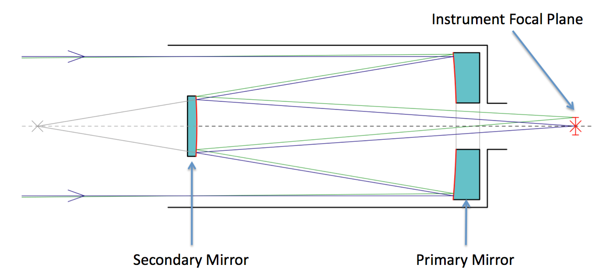 Figure 2. A schematic optical path for a typical Cassegrain telescope, such as the MMT. Light enters the telescope from the left, is reflected by the primary and secondary mirrors, then exits the telescope through a hole in the primary mirror.
Figure 3 shows the optical support structure, the primary mirror cell, and the secondary support hub for the MMT. The primary mirror is enclosed in a mirror cell, shown in the bottom of Figure 3. Eight trusses connect the support structures for the primary and secondary mirrors. A system of tension rods support the secondary mirror and its mirror hub at the front of the telescope. These rods must be as narrow as possible since they lie within the optical path of the telescope. This entire structure must be lightweight and structurally stable in order to prevent movement of the optics during telescope use.
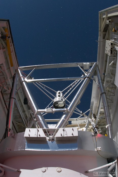
Figure 5 shows a simplied schematic diagram of the azimuth axis for the MMT. The entire entire telescope is supported on a concrete pier. Four large motors drive a series of gears to turn the telescope on the azimuth (horizontal) axis around this pier. This axis must work together with the elevation (vertical) axis to point the telescope in the correct direction and to track objects as they move across the sky.
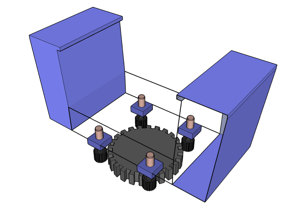
In addition, the telescope needs to rotate along its optical axis in order to compensate for apparent rotation of astronomical objects as the telescope tracks them across the sky. Each of these three axes for the telescope – azimuth, elevation, and rotator – require extremely high precision mechanical and electrical hardware as well as real-time controller software. The telescope must track an object within 0.1 arc-second (1/3600 of a degree) on the sky. Work is currently underway at the upgrade the azimuth axis with a new higher-resolution encoder and related software and electronics. A similar upgrade of the elevation axis was completed in 2008.
The MMT has a wide array of instruments to accompany the three secondary mirrors. These instruments are divided into cameras and spectrographs. The camera use CCD arrays to produce high resolution photos in the infrared and visible light wavelengths. The spectrographs measure the intensities of different wavelengths of light, typically to measure the composition and/or the red-shift of distant stars and galaxies. The red-shift is an indication of how fast the object is moving away from the earth. In general, each instrument is used with a specific secondary. With three secondaries and a dozen instruments, the MMT is one of the most versatile telescopes in the world. Secondaries and instruments are commonly changed every few days to match the scientific objectives of the visiting astronomers. A detailed description and listing of these instruments can be found at Instrument Suite Overview.